Home Assignments About Final Project

Rodrigo Shiordia

Week 12 Assignment: Application and Interface Programming


Programming an interface with Touch OSC Programming an interface with Processing and ControlP5 Setting up the development Board Group Assignment Assignment Files

Controlling a Stepper motor from the iPad using Touch OSC

Touch OSC Interface on the iPad!!!
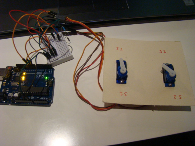

This was my setup:


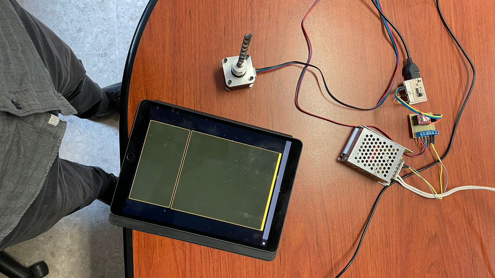
I have everything connected like this:
The ipad has a custom GUI that I made using Touch OSC Editor.
It sends Messages to the computer via WiFi.
The computer is receiving the messages in Processing using OSCP5, a special library that receives and parses the messasges.
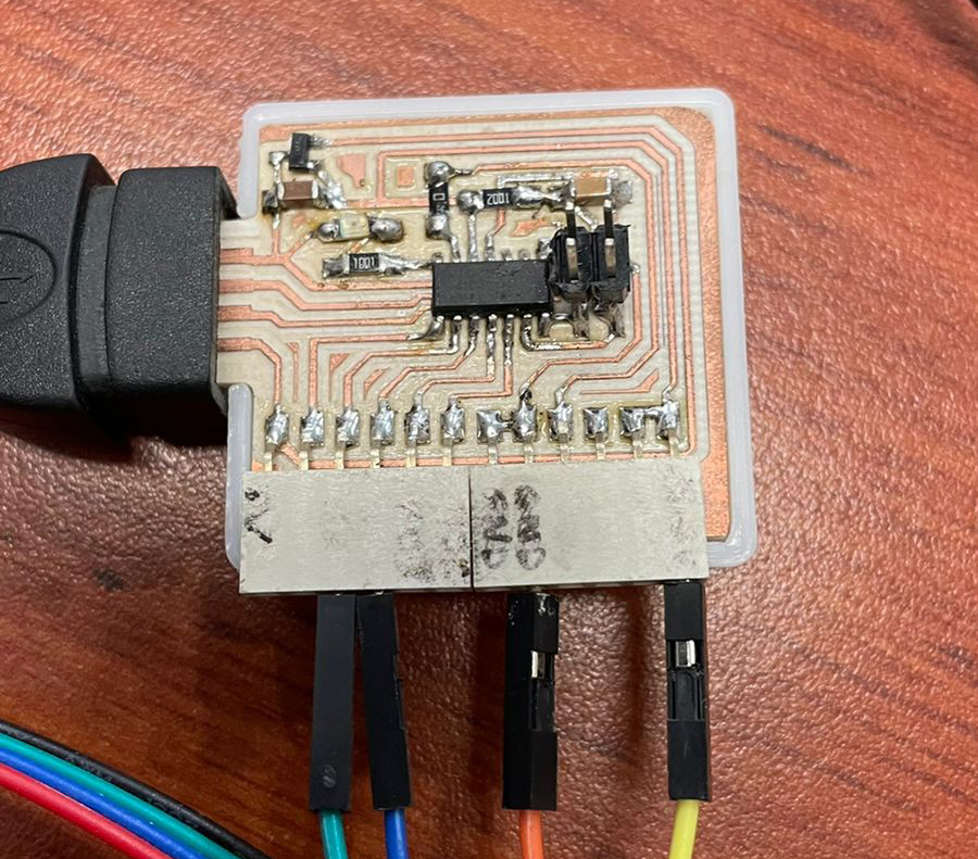
The computer is sending serial messages to a custom SAMD11C board.
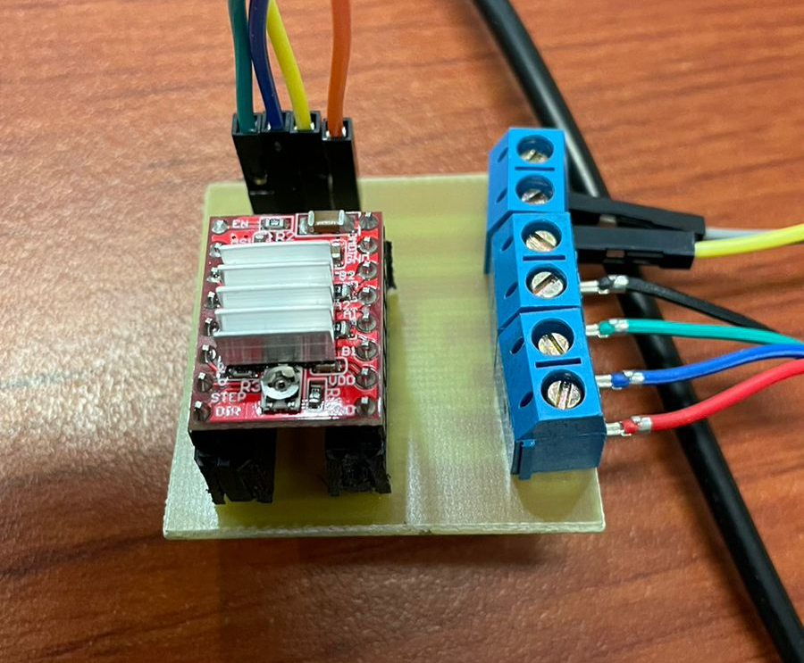
The SAMD11C board is sending pulses to a custom stepper driver module with a Pololu A4988.
The driver is pulling power from a 25V power supply.
The stepper is moving according to the driver's pulses

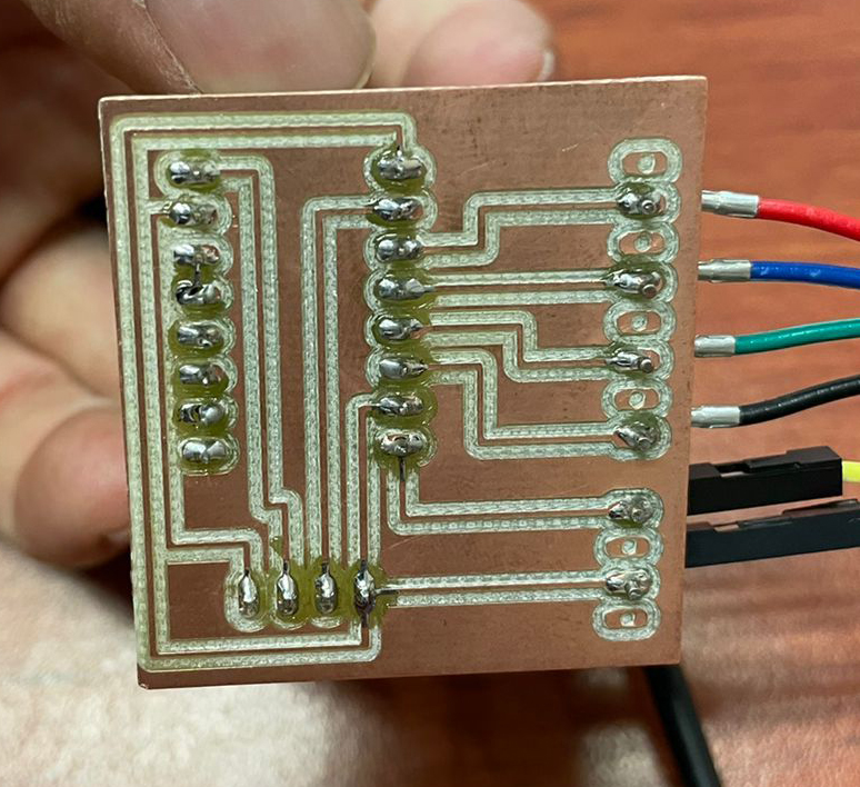
This is the controller board:


This is the stepper driver module:


This is the back of the driver module:

Touch OSC

TouchOSC is an implementation of Open Sound Control made by Hexler. It is an app to design and use control surfaces on iOS and Android. It sends and receives Open Sound Control or MIDI messages over WiFi. It also comes with the ability to create your own control surfaces or GUIs that you can configure using their free editor.

The first thing you do is download the app, which you can find on the app store.
What I did is to send messages from my iPhone or iPad to my laptop via WiFi using this app. The laptop then sends messages to my board using serial connection.
Once you have the app, you can connect to your computer using the computer IP address. 
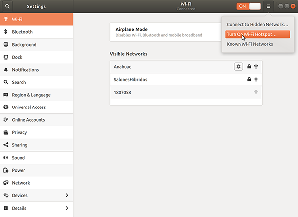
Since I was here at the university on the wifi network, I decided to create my own local area network. Using my Ubuntu system, I went to my WiFi settings and activated a local network using Turn On Wi-Fi Hotspot

You can do this on any WiFi network, but it's just easier and safer to send the messages over a local area network. After this, you connect the phone to this wifi using the provided password. Neither the phone nor the computer will have internet access after this point.
Once the phone is connected, you open the app, and connect to the computer using the computer's IP address.
in my case I just read the address from terminal using

ip address
To connect to the host computer on the app, you open the app, and then you just input the IP address of the computer under the Host Name field.


You'll notice that there is already an Interface loaded there. There are loads of examples with many different options.


Creating your Touch OSC interface using TouchOSC Editor
I used the editor in their webpage to create a very simple GUI that sends two values: an on/off value and a speed value that will be used by the stepper motor.
Once you download the editor you just start a new file, set up the resolution, and create objects. In my case I created a vertical fader object called fader1. I alse created a toggle button named toggle1. The fader's values will go from 500 to 20,000 which are the values I 'll use on the arduino side.


This interface is then loaded to the phone by pressing the sync buttom. On the app side, you tap "add" on the layout selector, and then add the Host IP address, it will download the interface you're working with.

Listening to messages from touchOSC using Processing OSCP5 library
Once you have done all this, you can start sending messages. Processing takes care of this, but it could be done in python or some other programming language.
You have your phone connected and every time you do something on the control surface of the phone or tablet, it sends an OSC message that the library OSCP5 interprets as an OSC event.
At first it's hard to parse the messages because you don't know if you are receiving, that's why I reccommend to use the examples from OSC p5. They will print to processing's console and you'll start to figure it out from there. And be very careful with the addresses and port numbers. of particular help is void oscEvent(OscMessage theOscMessage) which in the examples will print the type of event and some information that helps a lot.
I used the plug method to attach a function for the fader1 and toggle1. So every time you do something with them it reads the value of these elements in the GUI. And here is the code for the processing side:

note that I am importing two libraries: OSCP5 and Processing's built in Serial library.

                
                  /**
                  *Sketch by Rodrigo Shiordia Based on oscP5plug and crontrolp5 examples by andreas schlegel
                  fabacademy 2022 interface and application programming
                  */
                  import oscP5.*;
                  import processing.serial.*;
                  OscP5 oscP5;
                  Serial myPort;
                  int c =color(255);
                  boolean on=false;
                  int knobValue=5000;
                  void setup() {
                    size(400, 400);
                    String portName = Serial.list()[0];
                    println(portName);
                    myPort = new Serial(this, portName, 115200);
                    frameRate(25);
                    oscP5 = new OscP5(this, 8000);
                    oscP5.plug(this, "toggle", "/1/toggle1");
                    oscP5.plug(this, "slider", "/1/fader1");
                  }
                  void draw() {
                    background(c);
                  }
                  void oscEvent(OscMessage theOscMessage) {
                    if (theOscMessage.isPlugged()==false) {
                      println("### received an osc message.");
                      println("### addrpattern\t"+theOscMessage.addrPattern());
                      println("### typetag\t"+theOscMessage.typetag());
                    }
                  }
                  void toggle(float theValue) {
                    if (theValue==1.0) {
                      String s="H,"+knobValue+";";
                      myPort.write(s);
                      on=true;
                      c=color(255);
                    } else if (theValue==0.0) {
                      String s="J,"+knobValue+";";
                      myPort.write(s);
                      on=false;
                      c=color(0);
                    }
                    println(on);
                  }
                  void slider(float theValue) {
                    println(theValue);
                    int speed=int(theValue);
                    knobValue=speed;
                    String s="H,"+knobValue+";";
                    if (on) {
                      myPort.write(s);
                    }
                  }


The code on the arduino parses the serial message that Processing sends, and updates the stepDelay variable. note that Processing is sending things on this format:
H,700;
Arduino will read this string until it reaches ; , it will then split the string on the comma , and read the first part which will be "H" or "J". These letters will tell to turn the stepper on or off.
Then Arduino code will assign the number after the comma, and assign it to stepDelay.

                
                  int pulPin = 8;
                  int dirPin = 9;
                  int ledPin = 5;
                  int stepDelay = 700;
                  boolean on = false;
                  void setup() {
                    Serial.begin(115200);
                    pinMode(ledPin, OUTPUT);
                    pinMode(pulPin, OUTPUT);
                    digitalWrite(pulPin, LOW);
                  }
                  void loop() {
                    while (Serial.available()) {
                      String cmd = Serial.readStringUntil(';');
                      int comma = cmd.indexOf(',');
                      String stepVal = cmd.substring(0, comma);
                      if (stepVal == "H") {
                        on = true;
                      }
                      else if (stepVal == "J") {
                        on = false;
                      }
                      String stepSpeed = cmd.substring(comma + 1, cmd.length());
                      int val=stepSpeed.toInt();
                      if (val > 1) {
                        stepDelay = stepSpeed.toInt();
                        break;
                      }
                    }
                    if (on) {
                      digitalWrite(pulPin, LOW);
                      digitalWrite(ledPin, LOW);
                      delayMicroseconds(stepDelay);
                      digitalWrite(pulPin, HIGH);
                      digitalWrite(ledPin, HIGH);
                      delayMicroseconds(stepDelay);
                    }
                  }


Servo Control Interface Application

Arduino Servo Control

My final project will have some servos, so I used this week's assignment to work with since I didn't get to work with them on output devices week. The first thing I did was get them connected. Servos have an encoder, so they "know" where they are. They have three leads, one for GND, one for 5V and a control signal 5v. There are two kinds of servos, open and closed loop. Open loop is a continous servo that is a servo that can rotate more than 360°. Closed loop has a predetermined angle that it can go to. First lines of code were straightforward. I was up and running very quickly using the Servo.h library. Here is a picture of the connection, I will make this into a board when I'm back in the lab.

However the tough part was merging it with serial control. On the arduino examples, there's the Knob example that uses a potentiometer to control the rotation of a servo. I was at the same time researching Processing and ControlP5 library, and I found that CP5 has a knob object which was the exact same function. However, using it on the computer proved more difficult. The knob object writes to serial when moved. Here's a video of the servos working with the first try of the interface:


And here is the code for the processing side:

                  
                    import controlP5.*;
                    import processing.serial.*;

                    ControlP5 cp5;

                    int knobValue=90;
                    int knobValue2=90;

                    Knob myKnobA;


                    Serial myPort;
                    void setup() {
                      // fullScreen();
                      size(1500, 1500);
                      String portName = Serial.list()[0];
                      println(portName);
                      myPort = new Serial(this, portName, 9600);
                      cp5 = new ControlP5(this);

                      PFont p = createFont("Ubuntu", 60);

                      ControlFont font = new ControlFont(p);
                      cp5.setFont(font);
                      myKnobA = cp5.addKnob("servo_1")
                      .setRange(0, 180)
                      .setValue(90)
                      .setPosition((width/2)-500, height/2-500)
                      .setRadius(500)
                      .setDragDirection(Knob.HORIZONTAL);
                    }

                    void draw() {
                      background(0);
                      myPort.write(180-knobValue);
                    }

                    void servo_1(int theValue) {
                      knobValue=theValue;
                      println("a knob event. writing "+theValue+" to serial...");
                    }


Controlling servos independently, parsing command string in arduino

As you can see from the last example, every frame of the processing skecth, on the draw loop there's a funsction that writes an int to the serial. That lines is .write(180-knobValue)
That particular number is easily read by arduino, and written to both the servos, however, I cannot control them independently using two values or two knobs. I decided to use a comand-like syntax, a string to send to the arduino, and then parse it and get two distinct values on arduino. This was very difficult to me, but I finally got it running. This is the final arduino code:
This particular example has a very tricky thing that I spent a lot of time in. I couldn't find a solution online so I had to come up with one. I found some that were written in C but I couldn't understand them. The main thing is this: on the processing side, I will continously write to serial a string with this structure: servoValueA,servoValueB;. This is parsed ont he arduino code above. Particularly, I first use readStringUntil(';') to let arduino know that my command is sent. Then I use indexOf() to get the position where th comma is on the string. for example if the string is 90,180; the comma is on index '2' because first number has index '0'. Then, I use substring() to get the first and second values from the command. These values are then written to each servo pin.

                  
                    //expecting string in format: servoAValue,servoBValue;
                    #include 

                      Servo myservo;
                      Servo myservo2;

                      int A = 90;
                      int B = 90;

                      void setup() {
                        Serial.begin(9600);
                        myservo.attach(9);
                        myservo2.attach(10);
                        myservo.write(A);
                        myservo2.write(B);

                      }

                      void loop() {
                        if (Serial.available() > 0) {
                          String cmd = Serial.readStringUntil(';');
                          int comma = cmd.indexOf(',');
                          String StringA = cmd.substring(0, comma);
                          A = StringA.toInt();
                          String StringB = cmd.substring(comma + 1, cmd.length());
                          B = StringB.toInt();
                        }
                        myservo.write(A);
                        myservo2.write(B);
                        //uncomment for debuging:
                        // Serial.println(A);
                        // Serial.println(B);

                      }


Constructing and sending a command string event from Processing

On the Processing side, I used string concatenation of two variables to write the command string to the serial port. It's of particular interest to have the string formatted like we expect it on arduino.
Here is the final interface, where I'm controlling both servos independently almost on real time using two different knobs. There's a minute lag because of the time arduino takes to parse the string.


Here's the final processing code with both knobs:


                        ControlFont font = new ControlFont(p);
                        cp5.setFont(font);
                        myKnobA = cp5.addKnob("servo_1")
                        .setRange(0, 180)
                        .setValue(90)
                        .setPosition((width/2)-(knobRadii*2)-50, height/2-knobRadii)

                        .setRadius(knobRadii)
                        .setDragDirection(Knob.HORIZONTAL);

                        myKnobB = cp5.addKnob("servo_2")
                        .setRange(0, 180)
                        .setValue(90)
                        .setPosition((width/2)+(knobRadii*0)+50, (height/2)-knobRadii)

                        .setRadius(knobRadii)
                        .setDragDirection(Knob.HORIZONTAL);
                      }

                      void draw() {
                        background(0);
                        int A=180-knobValueA;
                        int B=180-knobValueB;
                        myPort.write(A + ","+B+";");
                        println(knobValueA + ","+knobValueB);

                      }

                      void servo_1(int theValue) {
                        knobValueA=theValue;
                        //println("a knob event. writing "+theValue+" to serial...");
                      }
                      void servo_2(int theValue) {
                        knobValueB=theValue;
                        //println("a knob event. writing "+theValue+" to serial...");
                      }


back to top

Setting up a development board

Digispark USB Development Board

I got the digispark because it features the ATtiny85 microcontroller. It ccomes with it's own firmware called micronucleus.
I installed the Arduino Core to upload directly using its USB interface. The instructions are here. For some reason, I had an unexpected problem, which was the version of micronucleus. I downloaded a new micronucleus and recompiled it and it worked as per the instructions in this thread.
With this set, I could now program the ATtiny45 directly from Arduino IDE.
Here's a simple schematic for the dev board:


This is the blink sketch. I will use more of this digispark in the future if I get the chance.


back to top